STRAKON 2020: Software for the Next Decade
With the new version 2020 the modeling and design software STRAKON from DICAD extends its functional range in important areas around structural design.
Sustainable software becomes better, more valuable and more comprehensive with each new version. The new version 2020 also expands STRAKON's range of services with additional functions - for example in architectural, engineering, precast element planning, reinforcement, cooperative BIM or 3D bridge planning. The new functions ensure more efficient process flows in companies and make planners fit for future tasks and challenges in the coming decade.
New 3D bridge construction concept
With the new bridge construction concept, the new version STRAKON 2020 perfects its extensive tool range with which even complex bridge superstructure projects can be easily created and flexibly modified. The route and gradient data required for the design can be imported or entered manually. Station planes can be defined along the 3D route generated from this data, on the basis of which standard cross-sections can be individually adapted. The bridge can thus be integrated into a digital terrain model. This allows even complex bridge superstructures to be conveniently designed in three dimensions.

If the route data is changed, the entire superstructure automatically adapts to the new route. The complete bridge substructure, such as piers or abutments, can also be easily integrated into this concept.
Work efficiently with 3D templates
STRAKON 2020 also offers clever solutions for the creation of identical or similar 3D components. For example, individual 3D objects with built-in parts and cube reinforcements can be saved in the library as flex parts. The flex part can then be integrated into a project and adapted to the current geometry requirements. For example, a pump sump consisting of various 3D objects and a cube reinforcement can be saved in the library. It can be individually adapted in its geometry during installation.
The advantage: Complex identical or similar objects do not have to be modelled several times and any existing cube reinforcements automatically adapt to the new geometry. If Flex components stored in the library are not broken down into individual objects during insertion, all inserted copies including cube reinforcement change automatically as soon as an inserted Flex component is changed.

Easier from 2D to 3D
A simpler modelling of storey buildings and better support in switching from 2D to 3D is made possible by the new "Planar Concept", which has been integrated into the orientation and control tool in STRAKON-Cube. Here, floor plans are entered planarly in the top view, which simplifies the 3D design process. Similar to 2D planning, the user works on a height level and can enter and edit objects in three dimensions. In particular, changing wall widths, heights and lengths in the plan view is made more convenient by new editing handles.
The new objects "Beam" and "Column" can be modified in a similarly intuitive way. In order for the user to know at which height level he is currently located, the heights of the structural levels are continuously displayed.
The cube wall has also been functionally expanded: wall heights can now be defined globally or locally using height nodes. Wall openings can now be defined at reference points with an improved input concept. A further function allows walls to be divided and the wall thickness of a partial wall to be changed. Also the new "SmartClick" in STRAKON-Cube allows faster working at different places, such as calling functions while taking over the parameters of the approached object or the elegant possibility to connect walls or lines, shorten them and generate intersections.
Faster from 3D model to 3D plan
STRAKON 2020 automatically generates correct 3D plans from the 3D model and relieves users of the time-consuming 2D drawing work. Default settings of the program ensure that floor plans, views and sections are displayed correctly. The engineer view function displays ceiling views in a manner suitable for engineers. Surfaces of rising components such as walls or columns are automatically marked with colour or standard hatching according to the settings, which increases plan readability. Openings and recesses are automatically marked with a cross or diagonal symbol in the 3D view. Objects and components can be labeled automatically in the plan. Surface properties of components are also displayed automatically, for example to mark the filling side of precast parts in the plan with a symbol.
Efficient cube reinforcement directly in the model
The so-called "cube reinforcement" has also been extended. In addition to the 3D reinforcement, it allows direct reinforcement input in the 3D model, automatically displays the reinforcement in 3D reinforcement views and positions it in the plan. In addition to a polygonal laying of bar steel, various standard bending shapes can be selected automatically for direct laying. The cube reinforcement automatically detects other existing reinforcement if required and adjusts the edge distance accordingly. A flat laying of steel bars is possible as well as free bending forms without the connection to formwork edges. With the new cube mats, laying fields can be defined and these can be laid out with reinforcement mats directly in the 3D model, taking into account previously made settings.

Comfortable working together
In order to work on a 3D project with several employees at the same time, models for the respective floors or construction stages to be worked on were previously created in different plans. Using so-called model references, each employee was able to see the overall model and use it in the team.
With the new STRAKON 2020 function "Project Model" the 3D model is generated within the work or project area, independent of the plan. This allows several employees not only to work on the overall model simultaneously, but also to edit the overall model across several sub-models, if they have the respective authorizations. As soon as an employee is active on a partial model, it is visible to others, but locked for editing. Once all employees have released the editing of their submodels, the entire model can be edited again, even across floors.
Integration in BIM and VR, ERP and PPS
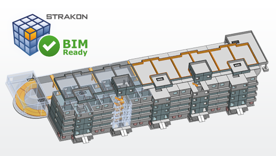
More and more often, projects are realized using the BIM planning method. For this purpose, 3D models including component data must be exchanged between the project participants via the IFC data format. STRAKON 2020 supports the IFC 2x3 and IFC 4.0 standard. The 3D reinforcement contained in the model is exchanged as "real" reinforcement with all properties such as diameter, position number, etc. as well as object geometries of 3D objects, flex components or built-in parts.
STRAKON 2020 now shows whether all objects were imported correctly during IFC import by means of a check log. If the IFC file is transferred to a VR presentation system, projects can also be viewed through VR glasses, including the material colors defined in STRAKON. STRAKON model data can also be exchanged with ERP, PPS and AVA systems, including all geometry, production and calculation data. To minimize data sizes, geometry data can be filtered out if required.
For STRAKON precast projects planned in connection with an ERP/PPS system, a new data synchronization enables a bidirectional data exchange. Thus, 3D/BIM data can not only be transferred to the ERP system, but can also be synchronized from the ERP system to CAD. This data can then be used in STRAKON for visualizations or list evaluations.
Parameterized 3D built-in parts
3D built-in parts can be positioned even more flexibly in STRAKON 2020 - either as a default, as the next free position or as a fixed project position number. Sub-items for 3D built-in parts can also be assigned. With the new parametric built-in parts, several copies, for example with different lengths, can be installed with one 3D built-in part. These lengths are then listed in the respective subitem in the installation parts list or added up as running meters. Reinforcements that belong to an installation part can now be saved as cube reinforcement in the 3D installation part. If a fixture is then installed in the model, the reinforcement is also automatically transferred to the steel list.
New architecture functions for structural engineers
Due to a growing demand, STRAKON continues to expand its range of functions in the direction of architecture for structural engineers. This area is becoming more and more important for DICAD customers - besides the fields of building construction, civil engineering, bridge construction, civil engineering and prefabricated construction - whose main business is structural design. For this purpose STRAKON 2020 has been extended by various functions, such as rooms: Both their types of use are now taken into account as well as wall and floor structures. Room data such as perimeter, area, room volume etc. can be supplemented with individual properties and automatically evaluated in a room list.

The automatic evaluation has also been extended for wall areas or object lists, which are automatically sorted according to the project structure per floor. A Flex parts list structured according to part types shows immediately how many similar parts are contained in the project, which simplifies the work of precast planners.
The project presentation has also been expanded: 3D projects can now be vividly presented including a realistic shadow representation in the form of perspectives or virtual tours.


Join Our Construction Experts in a Direct Exchange via a Free Online Live Presentation From STRAKON!
Ask for an appointment right here.
STRAKON Application Areas
- Construction Engineering
- Structural Design
- Structural Precast Parts
- Semi Precast Parts
- Architecture for Structural Engineers
- BIM
- Interfaces
More about BIM Planning
Experience STRAKON in Action
Why STRAKON from DICAD for structural engineers?
BIM planning
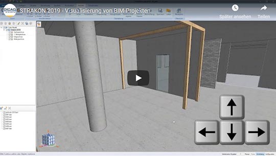
Visualization of BIM projects (DE)
Watch VideoBIM - Building Information Modeling
What is BIM?
BIM stands for Building Information Modeling. This planning process focuses in particular on cost security, adherence to schedules, quality improvement and sustainability.
Learn more about the topic "BIM":


